In this post we are going to briefly talk about the controlling method as well as the mechanism of the camera car. Please click here for you to have a fast recap of the project development.
The controlling method is relatively simple and straight forward. Unitilizing the wireless modules on the Intel Edison(Bluetooth/WIFI), direction signal sent from the controller is decoded as electrical power information(voltage), which drives the motors to spin for physical motions.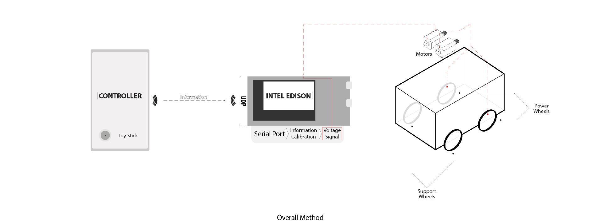
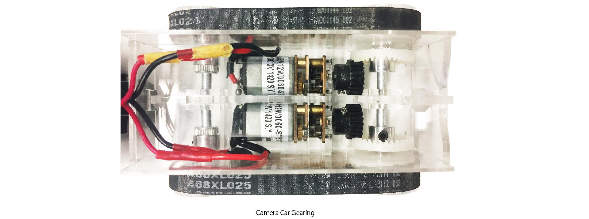
As mentioned before, in order keep the size of the car as small as possible, we use only two motors and they have to fullfill all the fundamental movements. There is a most common control mechanism for robot cars. The spin ratio of the two motors are individual from each other and due to the differetiated spin ratio, the camera car is able to perform movements such as moving forward and backward, turning left or right. This type of controling mechanism is called "Differential Drive". (You may find more control method information by this link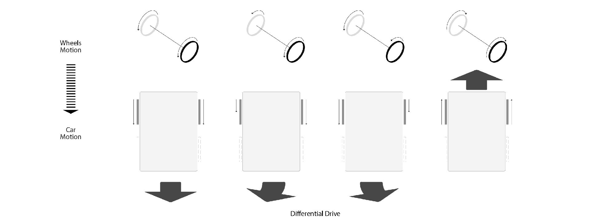
The next issue is how to send differentiaed electric signal from the controler. We can imagine the joystick as a point in a XY plane. The current position of the joystick can then be transformed into point coordinate value with a domain of -1.0 to 1.0 in both X and Y direction. And by a simple trigonometric function calculation, the distance between the current position with the origin as well as the angle between current position and X direction can be obtained. The distance value can be directly calibrated into voltage value that control the overall speed, while angular value is processed to calculate the spin ratio of left and right motors.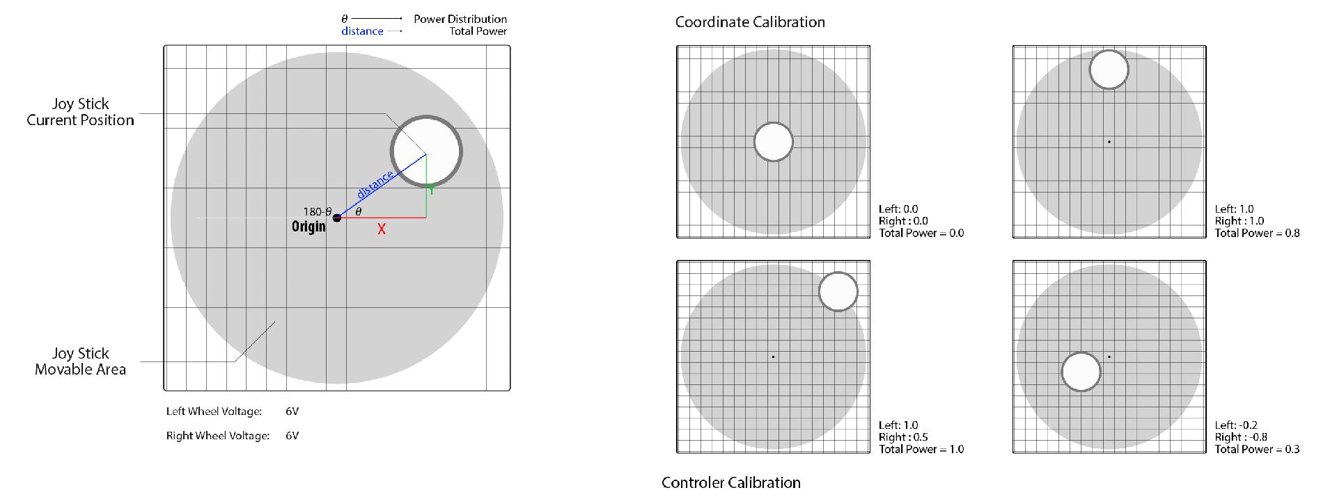
A superior controling mechanism is expected to be implement on the camera car, as it can only do the turns by moving forward or backward simultaneously, while the preferable one is that it can do the turns at its origianl locaiton as the limited space in the model.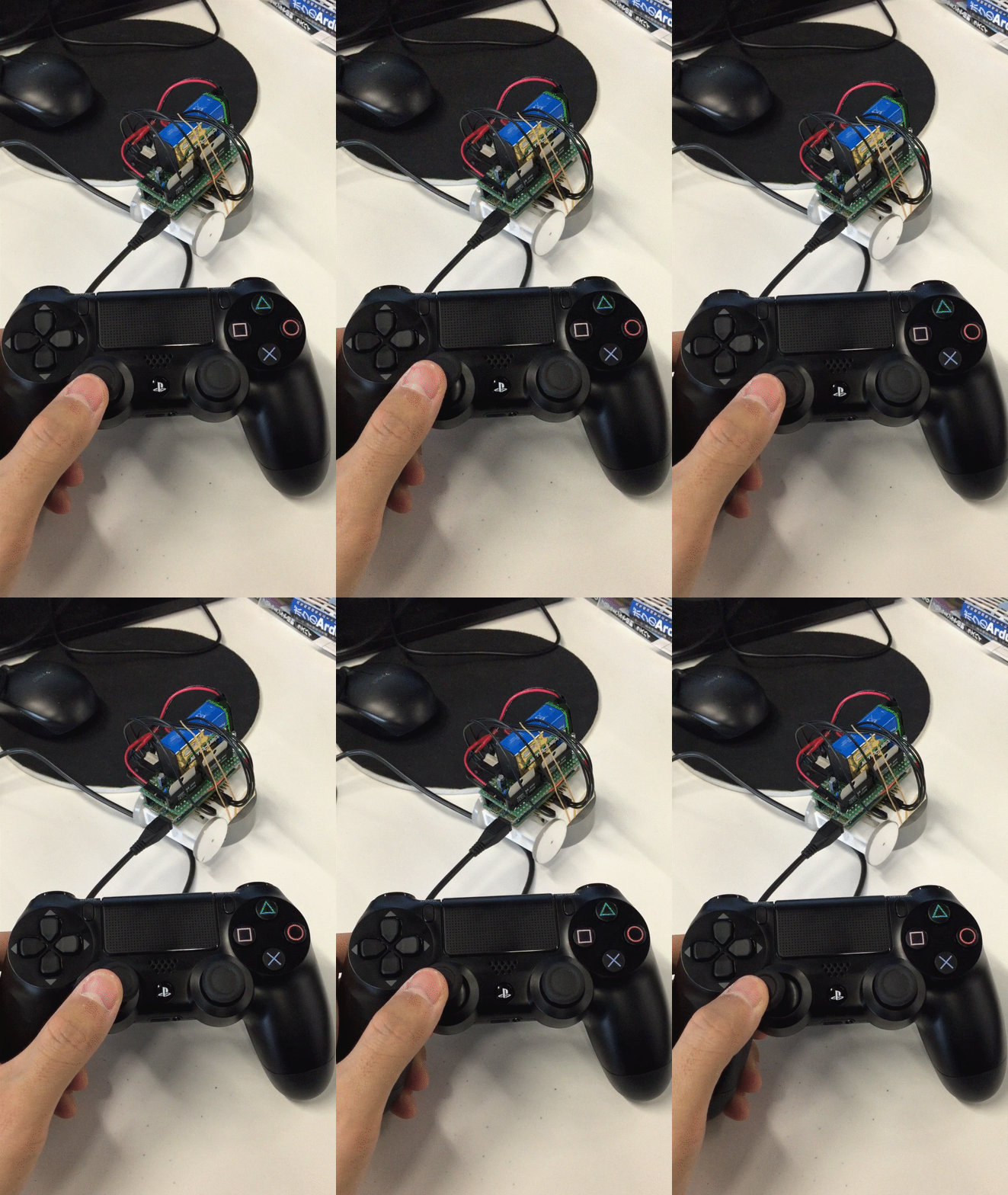


コメントをするにはログインしてください。